- AUDIO ONE-TO-ONE Call Now: 210-805-9927
- Contact
- Register
- My Account
Digital Audio Cables: How Can They Make a Difference? By Nordost Audio
The “Ones and Zeroes” Fallacy
We often hear the statement that digital cables can’t possibly make a difference in audio “because they are only sending ones and zeroes”. Dissecting that assertion, we can see a logical fallacy: a number is an abstraction and cannot be “sent”, but something that represents it can. Try as you might to give a friend a “1” or a “0”, it is impossible. But you can hand over a physical object or objects that represent the numbers you wish to transmit. So it is with the ones and zeroes (or bits) in digitized music. Bits are always represented by a physical system that can exist in either of two distinct states. When we store bits, the most common methods are magnets or transistors. For example, a music server’s hard disk uses billions of tiny areas that are independently magnetized (to represent a 1) or demagnetized (to represent a 0). In the case of a flash drive, microscopic transistors in “on” and “off” states represent the ones and the zeroes. Storing bits is the easy part. Sending them in real-time presents many technical challenges because a representation is being sent, in the form of a radio frequency electrical signal.
Squaring the Wave
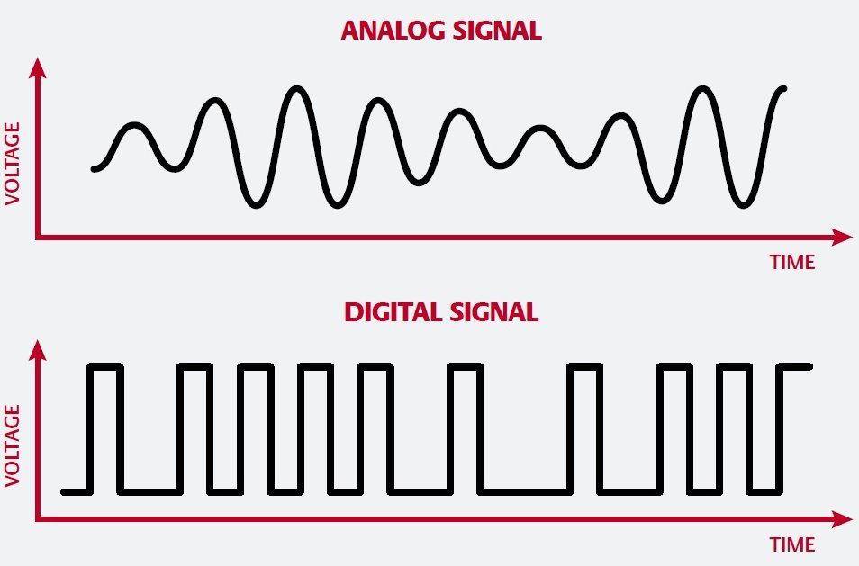
In digital audio data transmission, you can think of a bit as being represented by an electrical signal that alternates between two voltage states. This is unlike an analog signal, in which the voltage varies continuously, naturally mirroring the shape of the original waveform. While we tend to think of this signal as a perfect square wave with instantaneous changes between the two voltages, the reality is a little different. This is because the signal takes a finite amount of time to ramp up or ramp down. In modern digital audio sources, this “ramp time” is in the order of a few nanoseconds. This is fast but it is not instantaneous, which means that our “perfect” square wave has inclined sides and slightly rounded corners, resembling a trapezoid.
In electrical terms, a square wave is equivalent to a series of sine waves. Suppose for example that we generate a 60 Hz sinusoidal wave, then add its odd harmonics (3rd, 5th, 7th, 9th, 11th, and so on), we end up with a square-ish wave. As we add more harmonics, the corners of the square wave become sharper. The sharper we can make the corners, the easier it becomes for the receiver in the digital to analog (D/A) converter to correctly identify and time the incoming signal. Unfortunately, the sharper we make these corners, the more high-frequency content we introduce into the signal. This is exactly the content that we don’t want– otherwise our digital device turns into an FM transmitter! For this reason, the digital signal must be limited in bandwidth. Digital design is a careful balancing act to produce a signal that performs a square wave’s functions without its drawbacks.
A Real-Time Process That Can Cause Jitter
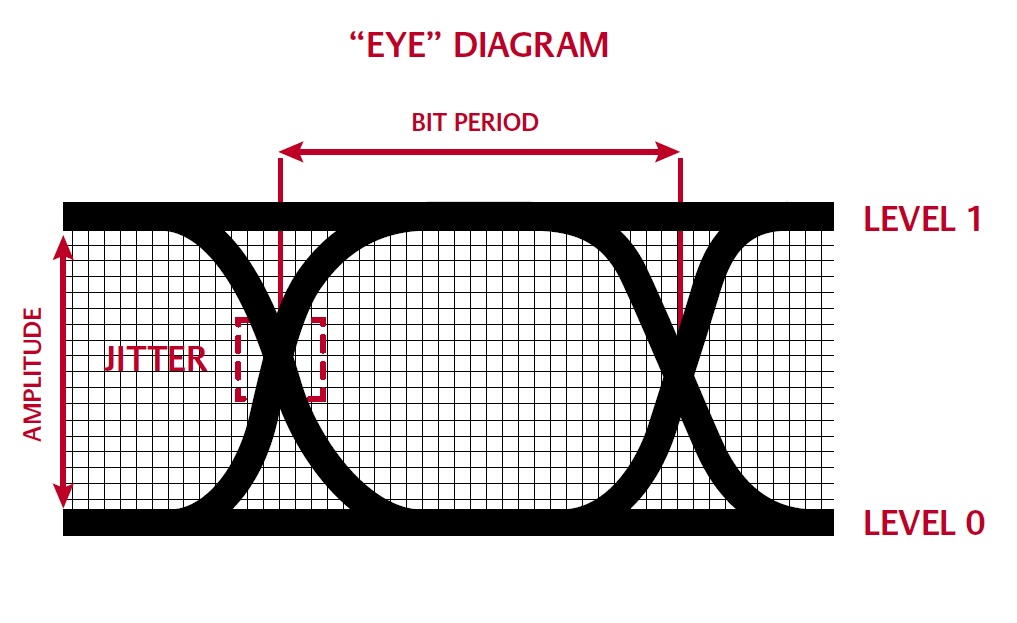
Now let’s take a moment to identify how these limitations can lead to problems in audio playback. Digital audio relies on precision clocks that time the digital samples during recording and during playback. Variation in the time at which data bits arrive is known as jitter, i.e., an error in clock timing. Jitter can be introduced at several points on the path from recording to playback. It can be embedded in the recording if timing errors occur during the capture of the original samples. This “recording jitter” cannot be eliminated during playback. The type of jitter that concerns us here is that which occurs in playback, as the data streams from the digital transport to the D/A converter. In digital audio, we are essentially converting timing information into frequency information. Thus, errors in timing become errors in frequency. Playback jitter introduces an effect called phase noise when the signal is reconstructed in the D/A converter, causing the music signal to be frequency modulated. The audible effects depend on whether the jitter is correlated or not with the audio signal. Uncorrelated jitter adds a broad-spectrum noise floor that clouds the music, reduces soundstage precision, and shortens the depth of field. Jitter that is correlated with the audio signal can result in peaks in the noise spectrum at discrete frequencies, which are more likely to be audible and objectionable. If a digital cable is not properly designed, it can blur the edges of the square wave signal or alter its shape to a significant degree. When this happens, the D/A converter’s receiver is less able to detect the transitions at the correct time, which results in jitter. To understand how this can happen, we need to look a little deeper at the nature of the signal that we are trying to preserve.
A Digital Signal is a Radio Frequency Signal
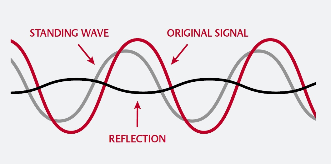
The rate at which the bit representations are being generated by a digital audio source means that the signal lies in the radio frequency (RF) range. Low-frequency signals, such as those transiting in analog interconnects, tend to behave themselves by staying within the boundaries of their enclosures. However, radio frequency currents behave very differently than currents transiting on analog interconnects. Firstly, energy from an oscillating current in the RF range can radiate off a conductor into space as radio waves. Secondly, because an RF current acts like a wave, it will tend to reflect off any discontinuities in the cable such as connectors and bends, and travel back down the cable toward the source. Any impedance mismatches will cause reflections. The amplitude of these reflections depends on the amount of impedance mismatch and the ramp time of the signal. These reflections can bounce back and forth several times between the source and receiver, causing standing waves that can confuse the D/A converter’s receiver as to the exact arrival time of data bits. In other words: jitter.
For these reasons, interconnects that carry RF signals require special consideration because they behave not as ordinary wires but rather as transmission lines. In designing a transmission line, the goal is to carry an electromagnetic signal (a wave that propagates within the cable) with minimal reflections and minimal power losses. This can be viewed analogously as a ‘tube’ that contains and guides the wave in a single direction, along its axis. This is precisely why, at Nordost, we terminate all of our 75 Ohm digital cables with BNC connectors. Unlike RCA connectors, which allow far too much swing on the 75 Ohm impedance, BNC connectors are designed to maintain the correct impedance of a transmission line. When using a component that requires an RCA connection from your digital cable, you simply use the BNC to RCA converter, included with all 75 Ohm digital cables.
How Cable Design Affects Audio Performance
For a digital cable to effectively do its job of propagating an RF wave with, minimal distortion and loss, its electrical characteristics must be carefully controlled. The most important characteristics to consider are the characteristic impedance, capacitance, shielding, and transmission speed.
Characteristic Impedance
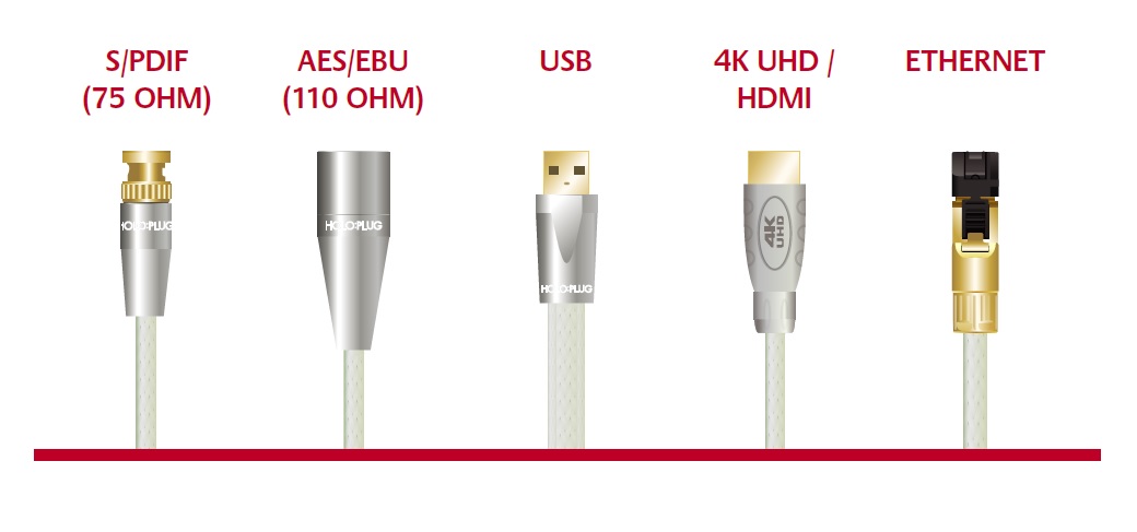
At low frequencies, impedance depends mainly on conductor size. At radio frequencies, however, the conductor size and geometry, insulation material (dielectric), and insulation thickness all affect the cable’s impedance. For transmission lines, the term “characteristic impedance” is used to describe the level of opposition that the line presents to the RF wave. It is defined as the ratio of voltage to current at the input to an infinite transmission line. Note that when an electromagnetic wave is reflected from the receiver back along the line and reaches the source, it interferes with the transmitted wave. Reflections, therefore, change the ratio of voltage to current at the input to the line, which will alter the characteristic impedance. The connectors of digital cables also form part of the circuit and must be certified as having the appropriate impedance for the application (75 Ω for S/PDIF, 110 Ω for AES/EBU, 90 Ω for USB, and 100 Ω for UTP Ethernet cables).
A final note on impedance– Although the focus here is on cables, from an electrical point of view, the transmission line includes more than the cable itself. It begins at the point where the RF signal is generated inside the digital source and ends where the signal is decoded inside the digital receiver. Thus, a transmission line includes the circuits before and after the connectors of the digital cable. If source and receiver circuit impedances are not precisely controlled by the manufacturer to the specified value, then even a well-designed digital cable cannot correct this type of impedance mismatch.
Capacitance
Digital cables typically have conductors arranged in a twisted pair or coaxial configuration. In either case, a capacitance develops between the conductors which contribute both to a phase shift (propagation delay) and crosstalk between them. Thinking back to our square wave, a cable with high capacitance will slow down the voltage transitions, so that the square wave comes out looking more like a sawtooth wave. High capacitance can also cause the signal edge to overshoot or undershoot and cause unevenness in the flat portions of the wave. This has obvious implications for the ability of the D/A receiver to correctly identify the edges of the wave.
Minimizing capacitance is one of the most important factors in designing a digital cable. This can be achieved by increasing the thickness of the dielectric insulation, decreasing conductor diameter, changing conductor geometry, and using an insulation with a very low dielectric constant, or a precisely formed foamed dielectric that leaves voids to mimic an air dielectric. Cable design is a careful balancing act, to ensure that capacitance is kept below levels that alter the shape of the signal, without altering the characteristic impedance.
Cable capacitance can be further controlled by three other methods. Firstly, appropriate damping to prevent resonant frequencies from vibrating the cable. Secondly, by use of low permeability (low leakage) dielectrics, such as fluorocarbon-based polymers (PTFE, FEP, or PFA). And thirdly, by using the best conductor materials that avoid oxidation on the surface of the conductor, since current flows primarily along the skin of a conductor at high frequencies. At Nordost, we choose to plate our copper conductors in silver for this very reason. To further protect against the harmful oxidation, all of our conductors go through a thorough chemical wash and ultrasonic cleaning before being insulated in FEP and continuing on to final assembly. However, we don’t stop there. Nordost’s engineers have developed another advantage over other companies– our proprietary mono-filament technology. By intricately and uniformly wrapping a single or twisted pair of FEP Mono-Filament around each conductor before encasing them in an extruded layer of high-quality FEP, each conductor is surrounded by its own air dielectric. In decreasing the interaction of the conductor to the insulation, the signal is no longer hampered (like it is in more traditional digital cable designs) and the speed of transmission is greatly improved.
Shielding
Cable shielding serves two functions: keeping RF signal inside the cable and keeping external signals out. Shielding is also part of the electrical circuit. Choice of shielding material and compatibility with audiophile connectors determine how the designer implements the shielding.
Transmission Speed
The effect that transmission speed has on digital cables is most easily explained by looking at USB cables. Finding a long USB cable can be a challenge. This is because most manufacturers are limited to producing 3-4 meter USB cables before they become unreliable. In order for USB cables to work, they (like HDMI cables) have to perform a digital handshake, where the signal travels from source to destination and then back in 26 nanoseconds. When using a conventional design, that handshake is only possible at short lengths. Nordost USB cables, on the other hand, employ Mono-Filament technology, enhancing signal speeds so much that we are able to build cables twice the length of a standard USB cable or longer, and still achieve a reliable handshake.
What to Listen For
Given that internal wiring and circuit board traces of digital audio components are not always impedance controlled, a digital cable that works well in one system may perform less well in another. As always, it pays to try different cables to find the one that works best in your system. A lower cable capacitance provides a richer sound quality with more of the natural brightness or “presence” of instruments. The better cables will bring about a lowering of the noise floor, which will translate to an increase in the clarity of a recording’s ambiance. Listen carefully to reverb, to how sounds echo and die away. Focus on the acoustic space around the musicians. Can you better notice subtle shifts in dynamics and in instrumental tone? Does it sound more natural and is there a better sense of timing? Does music seem more engaging or less? Can you listen longer with less auditory fatigue?
Summary
In digital audio, we are dealing with high-speed transmission of representations of ones and zeroes. Effective transmission of an RF wave without reflections depends on several factors. While impedance certainly matters, as mismatches can alter the shape of the wave or cause reflections, achieving a high velocity of propagation of the electromagnetic wave is a key design goal. Through well-considered choices of conductor type, conductor geometry, dielectric, shielding and terminations, digital cables can ensure that a correctly shaped and timed signal is received by the D/A converter, resulting in improvements to dynamics, tonality, and timing, removing irritants from the sound and allowing music to work its magic more effectively.
![]()