- AUDIO ONE-TO-ONE Call Now: 210-805-9927
- Contact
- Register
- My Account
DETERMINING PROPER AC POLARITY
Every component in an audio system is sensitive to AC polarity. Ensuring that your electronics are connected to the AC line with the correct polarity is essential if you want to realize the full potential of your system.
What follows is a simplified explanation of the phenomenon, and a description of a simple method of determining the proper connection of the power cord for any piece of equipment in your system.
All of the electrical equipment in your system has been designed with proper A/C polarity in mind. A specific leg of the A/C line has been dedicated as the positive (sometimes referred to as hot) conductor and the other leg as the negative (sometimes cold) or neutral. Often a third leg for ground, is included. The problem begins with the A/C wiring in our homes. If our electrical system is improperly wired we may not have the positive leg and neutral leg in their correct orientation. Coupled with design differences among equipment manufacturers, we have no way of knowing that correct AC polarity has been achieved by simply inserting the plug in the wall.
Technically, the transformer in the power supply can induce a charge (up to 90 volts) on the chassis side of each component. Interconnects allow currents to flow between all of the associated components in your system which is likely to modulate the ground reference of each consecutive gain stage. Proper 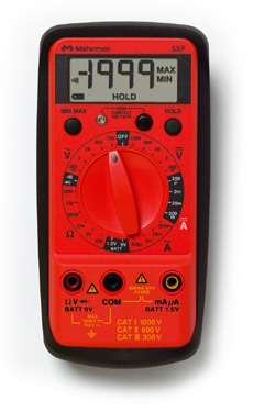 polarity alignment is achieved by registering the chassis potential to ground.
Correct orientation of the A/C plug (polarity) can be easily determined with a simple Multimeter or Volt Ohm Meter (VOM). One accurate enough to do the job (preferably a digital unit and one with a 10 to 11 Meg-Ohm input resistance). Home centers should have an appropriate model. A Multimeter can be used for a variety of tests and is something every audiophile or homeowner should have in their toolbox.
Before proceeding with the test, I would suggest you check all of your outlets for correct wiring. An electrical circuit tester (with three lights that tell you how the outlet is wired) is available in any home center or hardware store for a few Dollars.
To find AC polarity with your Multimeter, proceed as follows:
- Turn off all components.
- Isolate each component by removing all wiring including power cord, interconnects, ground leads, antenna wires, etc.
- On components with a 3 pin power cord, float the ground with a three-to-two adapter (often called a cheater plug or ground lift adapter). You can see a picture below. On many of these adapters the neutral side of the plug is usually wider than the hot side and reversing can be difficult. You may need to trim or file that side to allow reversal.
- Connect the common probe of the Multimeter (black lead) to a ground reference point*. I If you have a three-wire grounded receptacles, use the center pin.
- Connect the positive probe (red lead) to the chassis or ground terminal of the unit under test.
- Plug the component into the wall socket and turn on the power switch. Note the A/C voltage reading on the Multimeter.
- Reverse the position of the plug in the wall socket and repeat step 5.
- The correct A/C alignment will be the one that gave the lowest reading.
- Unplug the component, mark the plug so that you can properly reconnect it, and proceed to the next component.
If you find that the AC polarity of a component needs to be reversed, you have two options. One is to leave the adapter in place and the other is to change the polarity on the outlet itself. Please do not attempt this if you are not comfortable working with line voltages and be absolutely certain the breaker is off and there is no voltage at the outlet!
Please note that in some rare instances, the higher reading will produce better sound from the component. Listening to each and every component in the system can be an extremely lengthy process. And in some cases the differences will be so small that mistakes could be made. I would recommend for  most people to simply follow the meter. But if you want to get picky, listening tests should be employed to determine which is best.
Significant sonic improvements can be realized by the proper A/C orientation of all the components in ones system. The effect can be quite startling in some systems. Improvements in imaging, low level detail and high frequency clarity are often noted, with some components benefiting more than others. In my experience, preamplifiers and CD players (D/A converters included) are particularly sensitive to proper polarity, and often benefit greatly. Many tube units as well, seem to be rather sensitive to this phenomenon. It is important to do every component in the system, as improvements are additive. A little bit here and a little bit there adds up to a lot in the end.
* A good ground reference point may be difficult to identify. Try using a cold water pipe (do not use a gas pipe!), if you can locate one. An alternative method would be to use a copper grounding rod driven into the earth. The center receptacle of a three-wire system may not always represent a good ground reference. To verify its potential, connect the common probe to the ground receptacle. The positive probe then inserted into the hot receptacle should yield approximately 120 volts, the neutral receptacle should be less than I volt. If you find greater than a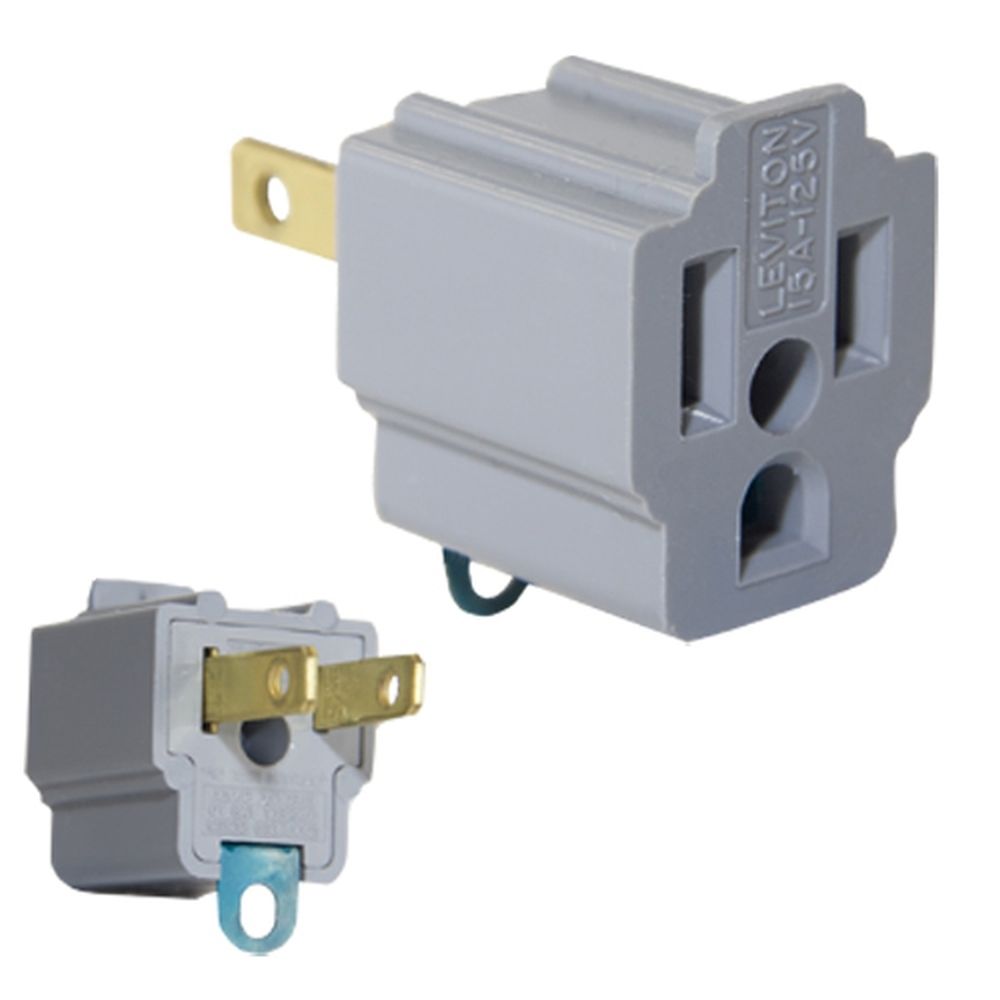 I volt differential, try an alternate ground. Some Engineers feel that the best method of grounding employs the use of a dedicated copper ground stake driven into the earth as near the equipment as is practical. All component chassis would then be tied to the stake with a heavy gauge wire, utilizing the star grounding approach, with either the preamp or amp as the star junction. Please be sure to follow all local electrical codes when attempting this type of an installation. This job may best be left to a qualified electrician.